Javys, a.s.
Technology
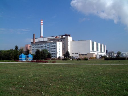
The A1 Nuclear Power Plant with its KS 150 heterogeneous reactor was designed to have an electrical output of 143 MW. Natural metallic uranium was used as fuel, heavy water was moderator and carbon dioxide was used for cooling. The reactor pressure vessel is cylindrical with a 5.1 m diameter and a height of 20 m. It was made from carbon steel and its wall is 15 cm thick. Inside, at the level of the active zone is another vessel made from an aluminum- magnesium-silicon alloy for holding the heavy water. This inner vessel is pierced by channels for holing the fuel assemblies and regulator rods. The reactor also has input and output coolant chambers and neutron and biological shielding.
A fuel assembly comprised a bundle of rods made of metallic uranium. The assembly was encased in a zirconium alloy protective tube. Each fuel assembly was placed in a technological channel, which was cooled by circulating carbon dioxide.
The primary cooling circuit consists of 6 loops, while each loop comprises one steam generator, a turbo-compressor and two parallel pipeline legs for hot and cool CO2 coolant. Individual loops of the primary circuit can be isolated from the reactor at both, the cool and the hot end, using section armatures. The carbon dioxide entered the reactor through 12 cool pipelines in the upper part of the pressure vessel. After entering the reactor, the gas was mixed in a cool gas mixing chamber. From here, it flowed into the individual technological channels, where it flowed around and simultaneously cooled the individual fuel assemblies. After the generated heat was taken away, it entered the reactor's hot chamber, where it was mixed together again and got out off the reactor through 12 hot pipelines. Through these hot pipelines the gas then entered the steam generators, where, at the secondary side, it caused water to evaporate and steam to superheat. The steam was then led into the turbine. From the steam generator, the cooled-down CO2 entered the intake of the turbo-compressor. From here the gas proceeded back to reactor through the cool pipelines.
Steam generators were designed vertically, consisting of a large number of U-shaped elements. Encased in an outer pipe with a 159 mm diameter, there were 19 small pipes with a 20 mm or 22 mm diameter, in-between which cooled-down carbon dioxide was flowing. Inside the pipelines, water from the secondary circuit was heated up and evaporated, or steam superheated.
Moderator cooling was ensured by 3 cooling loops, each consisting of 2 coolers and one D2O pump. The temperature of the moderator was kept at a maximum of 90 °C, at the reactor core. Heat exchangers were cooled by water from the primary circuit cooling towers.
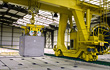
Facilities for putting together fuel assemblies and the facilities of the transportation-technological part, for handling fresh and spent fuel and its aftercooling and storing, formed a separate part of the A1 NPP compound. The facilities for aftercooling and storing of spent fuel assemblies included 2 short-term storage pools, a chamber for cutting the rods (on which fuel assemblies were hung in he technology channels in the reactor pressure vessel) and a long-term storage pool. Fuel assemblies, protected by long-term storage casings, were put into the long-term storage pool, filled with cooling water, by means of a refueling crane. At first the fuel inside the long-term storage casings was cooled by the Chrompik coolant, later by the Dowtherm organic coolant.
The main section of the secondary circuit of the power plant comprised 3 turbo generators, each with nominal output of 50 MW. The steam turbine was double-bodied, double-pressure, condenser type and it was always powered by two steam generators.