Technology
Scheme of WWER 440
The V1 Nuclear Power Plant with its WWER 440 type reactors was conceptually designed as two independent energy units. The technological design was double circuited.
Primary circuit
The primary circuit is that part of NPP facilities, where nuclear energy is transformed into thermal energy. The source of thermal energy in a nuclear power plant is the fission reaction taking place in the reactor's active zone. The active zone of the V1 NPP reactor contained 349 cartridges, 37 of which were control cartridges, 36 were imitators protecting the weld of the wall of the reactor pressure vessel from the radiation flux, and the remaining were fuel cartridges. Each fuel cartridge contained 126 fuel rods with uranium dioxide pastilles encased in zirconium alloy. The thermal energy was led out of the reactor by means of the cooling water, which used to flow around the fuel cartridges thanks to six circulation loops connected to the reactor. The main parts of the loop were the primary piping with the circulation pump, two shut-off valves and a horizontal steam generator. Cooled water in the primary circuit was returned from the steam generators back to the reactor’s active zone through the main circulation pumps, which kept the water circulating in the primary circuit. A volume compensator was incorporated into one of the circulation loops, for keeping the water volume changes in balance, as reactor's performance was changing and, simultaneously, the compensator kept the pressure of the cooling water in the primary circuit at a constant value.
Secondary Circuit
In the secondary circuit, thermal energy of the steam raised in the steam generators is transformed into mechanical energy at the turbine. Each V1 NPP unit had two turbines, each of which had a power output of 220 MWe. The turbines had a high pressure segment and a doubled low pressure segment. The expansion of the pressurized steam between the rotor blades made the rotors turn. After expansion in the low pressure segments, and temperature reduction, the steam in the turbines condensed and became water again. The condensed liquid from the steam was led back to the steam generators, where it was vaporized again and again fed to the turbines. The water and steam cycle in the secondary circuit was closed. The mechanical energy was transformed into electrical energy at the generators, the rotors of which were fixed to the rotors of the turbines. The generators’ brackets provided electricity at a voltage of 15.75 kV, which was subsequently transformed to 220 kV to be distributed to the grid.
Circulating Cooling Water Circuit
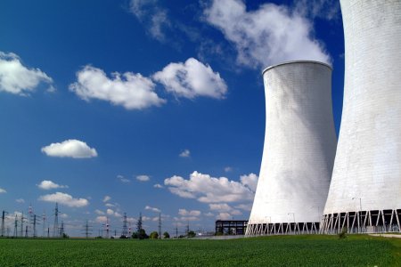
For a more efficient thermal to mechanical energy conversion, the condensers cooled down under the low pressure parts of the turbines, where only the unusable energy of the water was dispensed, what was done by a third, so-called circulation cooling water circuit of the power plant. This circuit was connected to the cooling towers, where the water, heated up at the condensers, cooled down. While the primary and secondary circuits were closed, the circulation cooling water circuit was open. The cooling towers released water vapor and small water droplets into the air and thus the system had to be fed by additional processed cooling water from the Váh river.


